Back to contents
User interface
kHED has a classic 3D-editor interface. It consists of four viewports (display areas), and toolbars. Each toolbar can be moved or attached to any edge of the window by dragging it with mouse cursor. You can show or hide panels through the View menu.
The application main window is shown below:
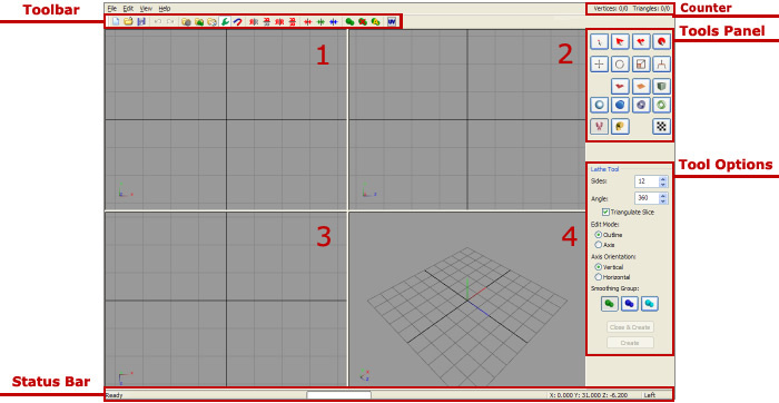
Viewports 1, 2, 3, 4
Each viewport is an image of a model with certain settings. First of all it's a type of projection: orthogonal (2D) and perspective (3D). Orthogonal projection is similar to that used in technical drawing, and perspective is similar to human vision.
By default, 1, 2 and 3 are orthogonal and displaying the model from front, left and top respectively. Viewport 4 displays the model in the perspective projection. To find out what the projection is selected, place your mouse pointer on a viewport: the current projection will be shown in the status bar.
To customize viewport options you can click on it with the right mouse button.
First 4 lines are model view modes:
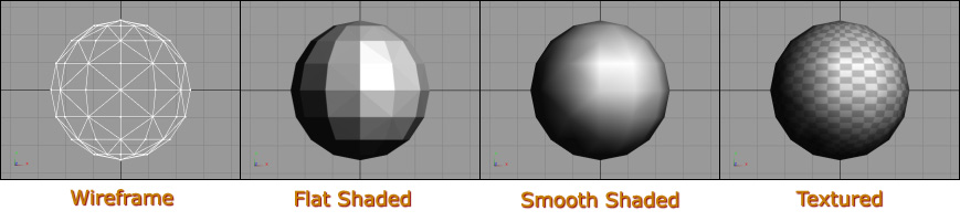
Wireframe Overlay - turns on drawing the wireframe over the model. This setting has no effect in Wireframe mode.
Draw Backfaces - turns on triangle backface drawing.
Front, Back, Left, Right, Top, Bottom - direction of the orthogonal projection.
3D Rotate - The rotation around the origin.
3D Look - "First person" view. In this mode you can navigate in the space with the arrow keys.
Options... - Open "Viewport options" window.
Reset View - Set view direction to the origin.
Maximize - Maximize viewport to all working area.
Background Image - Choose a background image for the viewport. This is useful when creating a model by a photo or sketch. To remove the background image, select Remove Background Image (available only if a background picture is set). If at least one background image is set, Edit Background Image function is available in View menu. It allows you to move, rotate and scale the background image.
The 3D window has also three additional control buttons. They allow you to switch between different viewing modes: rotation around origin, rotation around selection and "First Person", respectively
You can zoom the view with mouse wheel or with Shift and the left mouse button.
You can pan the view with middle mouse button or with Ctrl and the left mouse button.
You can also resize the splitter between viewports. Double-click on the splitter to restore it's original position.
Toolbar

This panel offers the following features (from left to right):
- New - Create new file (also available through File->New or Ctrl+N)
- Open - Open file (File->Open, Ctrl+O)
- Save - Save file (File->Save, Ctrl+S)
- Undo - Undo the last action (Edit->Undo, Ctrl+Z)
- Redo - Redo the last cancelled action (Edit->Redo, Ctrl+Y)
- Groups - Open/close groups panel (View->Groups, G)
- Smoothing Groups - Open/close smoothing groups panel (View->Smoothing Groups, S)
- Materials - Open/close materials panel (View->Materials, M)
- Tools - Open/close tools panel (View->Tools)
- Snap To Grid - Turn on/off snapping to grid (Click the right mouse button to select the step of snapping)
- Mirror Horizontal - Mirror selected objects horizontally (Edit->Mirror->Horizontal)
- Mirror Vertical - Mirror the selected objects vertically (Edit->Mirror->Vertical)
- Mirror Clone Horizontal - Create a horizontally mirrored copy of selected objects (Edit->Mirror->Clone Horizontal)
- Mirror Clone Vertical - Create a vertically mirrored copy of selected objects (Edit->Mirror->Clone Vertical)
- Flatten X - Flatten selected vertices by X axis(Edit->Flatten->X)
- Flatten Y - Flatten selected vertices by Y axis (Edit->Flatten->Y)
- Flatten Z - Flatten selected vertices by Z axis (Edit->Flatten->Z)
- New Smoothing Group - Assign selected triangles to new smoothing group
- Remove Smoothing - Remove smoothing from selected triangles
- Auto Smooth - Opens an automatic smoothing dialog box
- UV Editor - Open the UV Editor
Status Bar
Displays the current action, its progress, the current coordinates and the projection.
Tools Panel
There are buttons for selecting tools on this panel. They include the selection, modification of the geometry of objects, creating objects and projecting texture coordinates. (see Tools for more information)
Tool Options
This area shows the options of the current tool. (see Tools for more information)
Counter
It displays the number of vertices and triangles of the model. In the program settings you can also configure how this counter will display selected or hidden objects.
Back to contents