Back to contents
Tools
To select a tool, click on the appropriate button on the tools panel.
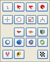
Select Tool

This tool allows you to select certain model objects. The four buttons correspond to the four modes of selection:
- Vertex (1 key) ;
- Triangle (2 key);
- Polygon - group of coplanar triangles (3 key);
- Group (4 key);
In the triangles, polygons and groups selection mode there is By Vertex option available, that tells that the objects will be selected only if their vertices are selected.
In the groups selection mode there is available Group/Smoothing Group option, with wich you can choose the type of the group you want to select.
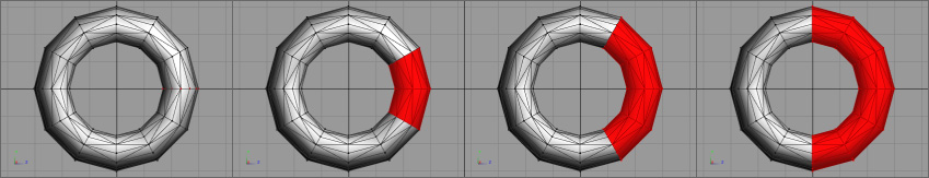
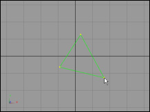
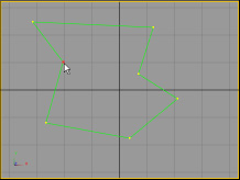
The Grow function is available in all modes. It selects the triangles with vertices selected. Here's the example:
To select an object, click on it with the left mouse button in any viewport. To select a few objects, hold Shift and press the left mouse button on each one of them.
To deselect an object, click on it with the right mouse button while holding Shift.
It is also available to select objects using frame in the orthogonal (2D) viewports. Hold the left mouse button and drag the pointer to select multiple objects. Hold Shift and the right mouse button and drag the pointer to deselect multiple objects at once.
Move Tool (Q)

This tool moves the selected vertices.
To move the selected vertices, hold down the left mouse button in any 2D-projection, and drag the pointer. If you select this tool, all 2D-viewports display arrows showing what axes the movement will be applied on:
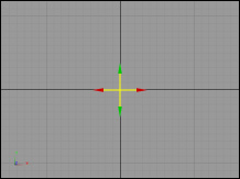
Active axis are marked in yellow. To move objects on one axis, hover your mouse pointer on the corresponding arrow, then move the pointer while holding the left mouse button.
It is also available to move objects in a certain distance, entered in the input fields. Enter the appropriate values and click Move or press Enter to move objects.
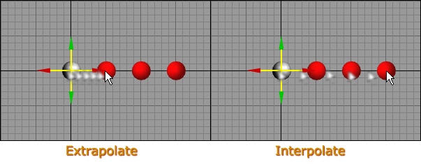
The Clone option allows you to create an arbitrary number of object copies at a specified distance. Enter the number of copies in the Number of clones field and select the mode of distance calculation Interpolate or Extrapolate. See Figure:
Rotate Tool (W)

This tool rotates the selected vertices around the specified axis (pivot). When selecting a tool, 2D-viewports show the axis of rotation:
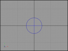
To rotate objects, drag the left mouse button in any 2D-projection. To move the axis of rotation, hover your mouse pointer on the circle and move the axis holding the left mouse button.
It is also available to automatically set the axes of rotation with the buttons in the tool options:
- Bounds Center - center of dimensions of the selected vertices;
- Simple Average - a simple average of the selected vertices;
- Origin - origin of the coordinates;
You can choose the angle step with the Snap Angle option.
Clone option is identical to Move Tool clone option.
Scale Tool (E)

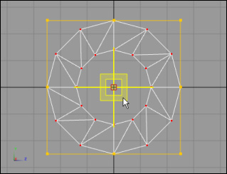
This tool allows you to scale the selected vertices. When this tool is active, all the 2D-viewports show the scale frame and the cross representing the scale pivot point.
You can scale objects in several ways:
- In any area of any 2D-viewport (along two axes);
- With one of the cross axes (along one axis);
- With the scale frame (along one or two axes);
- Uniformly with special fields (along two or three axes).
Use this field to uniformly scale objects along three axes:
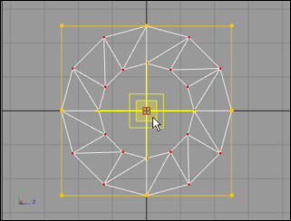
You can move the pivot point by dragging the cross center or with the Set Pivots buttons in tool options:
- Bounds Center - center of dimensions of the selected vertices;
- Simple Average - a simple average of the selected vertices;
- Origin - origin of the coordinates;
You can also use Half and Double buttons to scale objects.
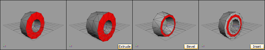
Extrude Tool (R)

This tool includes three "sub-tools":
- Extrude;
- Bevel;
- Inset.
The following options are available in Extrude mode:
- Leave Original - leave a copy of the original triangles (a copy is reversed in the opposite direction). This is useful for turning plane objects to three-dimensional;
- Direction - direction of extrude. When it is By Normals, vertices are extruded along their triangles normals. When the direction is Linear, the vertices are moved as in Move Tool;
- Auto Smooth - if checked, the side triangles are assigned to smoothing groups, chosen by maximum angle between them (By Angle). Or all the side triangles are assigned to single group (Single Group).
Polygon Tool

This tool has three modes:
- Triangle;
- Polygon;
- Complex Polygon - it can have holes and a specific topology.
The polygons are created in same way. Except for the fact that all vertices should be created in that viewport, where the first click had been made. Edges of the polygon should not intersect.
Click on the first vertex of the polygon to finish building a polygon. After this, the triangulation (subdividing a polygon to triangles) will be applied.
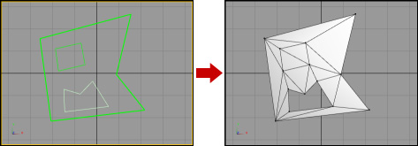
When in Complex Polygon mode, the polygons are created by steps: first you specify the polygon outline, just like in Polygon mode; then you create inside edges.
After the outline is finished, new options become available:
- Fill - the inside polygon will be filled with triangles;
- Hole - the inside polygon will be a hole;
- End Line - with this button you can end line without closing it;
- Triangulate - apply the triangulation.
New triangles are facing the projection, in which they were created. You can check Two-sided flag if you whant the triangles to be created in two copies with different orientation of the front side.
Plane Tool

This tool creates a flat rectangle facing to the current projection.
Enter the number of segments in height and width to the input fields Rows and Columns respectively. Use the Turn Edge option to control the rotation of diagonal edge:
- No;
- Each Row;
- Each Column;
- Each Column And Row.
You can see the results in Preview field.
To create a plane, hold the left mouse button and drag the pointer in any of the 2D-viewports.
Box Tool

This tool creates a box or a cube.
Creating a box is carried out in several steps (depending on options). By default, this process consists of two steps. The first one sets the Width and Height with dragging the mouse pointer in one of 2D-viwports, the second step sets the Length.
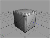
When Fillet segs is greater than zero, there's also a step, at wich the Fillet value is set:
A box with a fillet (Fillet segs = 3):
Height Stacks, Width Stacks and Length Stacks options allow you to set the number of segments along height, width and length respectively.
When the Cube flag is checked, the width, height and length values will be equal.
The current width, height, length and fillet value are displayed on the status bar.
Sphere Tool

This tool creates a sphere.
Two algorithms for constructing sphere are available: Sphere and GeoSphere:
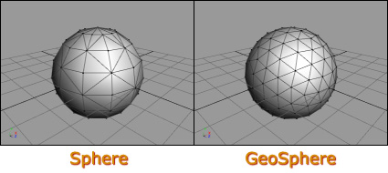
The Sphere mode needs the number of Sides and horizontal segments Stacks to build a sphere. The GeoSphere needs the number of Iterations: the greater this number is, the greater will be the number of sphere triangles.
To create a sphere, hold the left mouse button and drag the pointer in any of the 2D-viewports. Location of the sphere center depends on Creation Method option.
Cylinder Tool

This tool creates a cylinder.
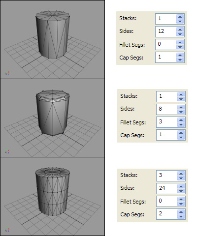
The following parameters are available for the cylinder:
- Stacks - height segments;
- Sides;
- Fillet Segs;
- Cap Segs.
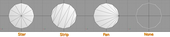
The Cap Type option specifies the type of cap triangulation:
The cylinder position depends on Creation Method option.
Tube Tool

This tool creates a tube.
The tube can have following parameters:
- In Stacks - height segments of inner radius;
- In Sides - the number of sides of inner radius;
- Out Stacks - height segments of outer radius;
- Out Sides - the number of sides of outer radius;
If the inner radius of the tube is much smaller than the outer, it is useful to reduce the number of sides on the inner radius to lower the total number of model triangles.
The tube position depends on Creation Method option.
Torus Tool

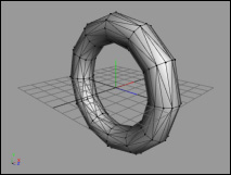
This tool creates a torus.
The torus can have following parameters:
- Sides;
- Segs;
The torus position depends on Creation Method option.
Lathe Tool

This tool creates a rotational body by a given outline:
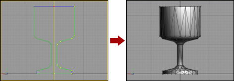
The number of body sides is controled by Sides parameter.
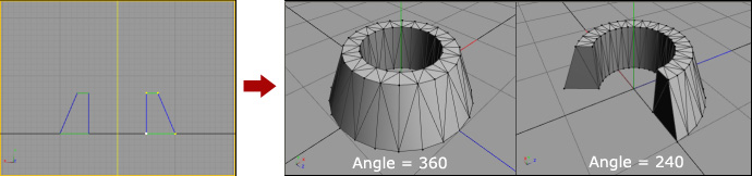
The angle of rotation is set by Angle parameter and the default is 360 (complete turnover). If the angle is less than 360, the body will have a slice. Triangulation of the slice is controlled by Triangulate Slice option.
Two edit modes are available:
- Outline - editing the outline;
- Axis - moving the axis;
The Smoothing Group option allows you to pre-assign segments of the outline to a certain smoothing group. The segments are colored accordingly.
The lathe is created when you close the outline, or by pressing buttons Create or Close & Create. The latter one closes the outline before creating a lathe.
If the outline is not closed, the body may be "turned inside out". To correct it, use the Edit -> Reverse Vertex Order function.
Loft Tool

This tool can be used for different purposes. It is similar to multiple Extrude by a given path (outline).
To create the loft you need to specify the outline and section. By default, the section is a circle, the sides number of which controled by the Sides parameter.
You can also modify the shape of the section. To do this, click the left mouse button on the section view field. This will lead to opening the Section Editor dialog box.
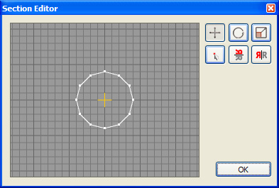
The tools of this dialog box allow you to move, rotate and scale the section relative to the center. You can also mirror the section horizontally and vertically. Use the Move Vertex tool to move separate section points with the mouse pointer.
The following modes are available when creating the outline:
- Outline - editing the outline;
- Fillet - editing the fillet value;
- Section Scale - editing the section scale;
- Section Rotate - rotate the section;
The Fillet Segs parameter sets the number of smoothing segments at the corners of outline.
The Close Caps options turns the caps triangulation on.
The Close Outline button connects first and last outline points to create a closed shape.
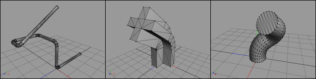
See the examples of the Loft Tool use below:
Mapping Tool

This tool is designed for projection of texture coordinates, as well as automatic texture unwrapping.
You need to select some triangles, for wich the texture coordinates will be calculated, before you use this tool.
The following projection types are available:
- Planar;
- Cylindrical;
- Spherical.
It is also possible to orient by the normal of any model surface. To do this, hover the pointer on the desired surface in perspective (3D) viewport and click the left mouse button.
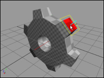
To apply the texture projection press Remap button.
There are also available two algorythms of texture automatic unwrapping:
- Unfold - all the triangles are turned to the same plane, forming one continuous element;
- Flatten - triangles are divided into different elements and the planar projection is applied to each of them;
After clicking on one of the buttons for automatic unwrap, the dialog box opens, which displays the current unwrap. Here's an example of unwrap for a cylinder:
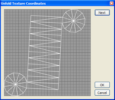
Click Next to set the next triangle as the starting. In some cases it can help to make better unwrap.
Click Ok to apply the unwrap.
When unwrapping mode is Flatten, this dialog box has also the Max. Angle parameter, which determines the maximum angle at which the triangles may belong to one element.
Typically this tool is used in combination with manual editing of texture coordinates (see UV Editor).
Back to contents